
This is an old revision of the document!
Table of Contents
Honda NTV650 Revere - Wiring diagram
Here it is the wiring diagram drawn in color. It was derived by me from a black and white printed diagram from Honda. Inspecting the original drawing I spotted two erros: there were two missing joints. Both were in the main harness, one on the green wires and the other in the white/green wires.

Here it is the the PDF version: Honda NTV650 Revere wiring diagram (PDF).
Headlight wiring


Harness wires gauge
Inside the main wiring harness you will find at least three types of cables; they are stranded cables of different gauges, these are the specifications:
| Outer diameter | Number of strands | Strand diameter | Cross-sectional area | AWG equivalent | Ampacity | Load | |
|---|---|---|---|---|---|---|---|
| Thin | 1.70 mm | 20 | 0.16 mm | 0.40 mm² | 21 AWG 20/34 | 2.9 A | 35 W |
| Medium | 1.85 mm | 30 | 0.16 mm | 0.60 mm² | 19 AWG 30/34 | 4.3 A | 52 W |
| Thick | 2.65 mm | 37 | 0.25 mm | 1.82 mm² | 15 AWG 37/30 | 13.0 A | 156 W |
The outer diameter refers to the overall cable, including the insulator. The AWG gauge is calculated measuring the diameter of the single strand and calculating the overall cross-sectional area; then the nearest value is looked into the AWG gauge table.
NOTICE: The 19 AWG 30/34 notation means that there are 30 strands, each strand is an AWG #34 wire (0.160 mm diameter), the overall cross-sectional area is 0.60 mm², wich is almost an AWG #19 wire.
NOTICE: The ampacity reported in the table is the maximum electrical current in amperes that the conductor can carry for 2 meters, mantaining the voltage drop below 2%. The formulas for calculating the voltage drop for a copper conductor (coefficient ρ = 1.68*10^-8 Ωm) are:
- cable resistance Ω = (1,68 * 10^-8 Ωm) * (cable lenght m) / (cross sectional m²)
- voltage drop v = (current A) * (cable resistance Ω)
Web References
Insulating tape
The main wiring harness is assembled using extensive electrical tape, both for the external wrapping and to insulate some internal connections. These are the characteristics of the tapes used:

| Color | Width | Thickness |
|---|---|---|
| Black | 20 mm | 0.10 mm |
| Blue | 40 mm | 0.20 mm |
The black tape is very soft and flexible, unlike the ones commonly found on the market which have a thickness of 0.13 or even more.
Connectors
The mini connectors used into the wiring harness are the MTW Sumitomo unsealed series, with 2.8 mm terminals. Here are the part numbers:
| Sumitomo MTW series | |
|---|---|
| 6040-2111 | Housing Female, 2P |
| 6030-2981 | Housing Male, 2P |
| 6040-3111 | Housing Female, 3P |
| 6030-3991 | Housing Male, 3P |
| 6040-4111 | Housing Female, 4P |
| 6030-4991 | Housing Male, 4P |
| 6040-9111 | Housing Female, 9P |
| 6030-9991 | Housing Male, 9P |
| 1500-0071 | Male terminal 2.8 mm, tinned brass |
| 1800-2097 | Male terminal 2.8 mm, nickel-plated copper |
| 8240-4092 | Female terminal 2.8 mm, tinned brass |
| 8240-4050 | Female terminal 2.8 mm, nickel-plated copper |
| Sumitomo 4 mm bullet series | |
| 7230-5873 | 4mm Sealed Bullet Plug |
| 7210-0011 | 4mm Sealed Bullet Receptacle |
Here you can download the Sumitomo MTW series conntector catalog. Beware of the thickness of the male terminal: it original is 0.5 mm, whereas you can find many low quality replicas that are only 0.3 mm.
Fuel pump connector polarity
After disassembling the carburetors you may want to force the fuel to fill them again. Using the start button and letting the entire engine rawwing for a long time may be an high load for the battery, so you may prefer to provide 12 V directly to the pump connector.
In this photo you see the polarity (red is positive and black is negative) of the connector from the wiring harness to the pump:

You will hear the noise from the working pump. Once the carburetors are full, the pump will stop.
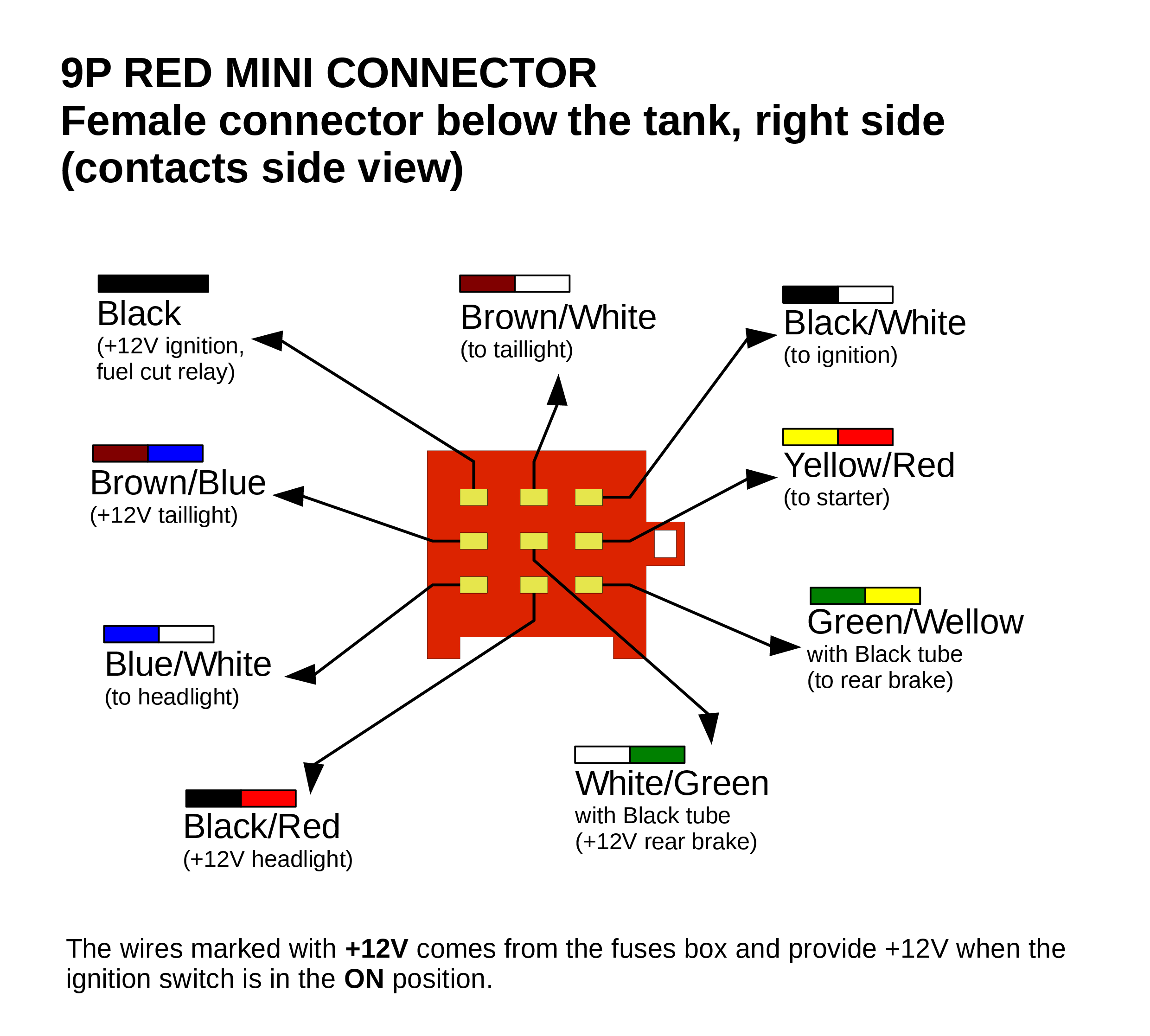
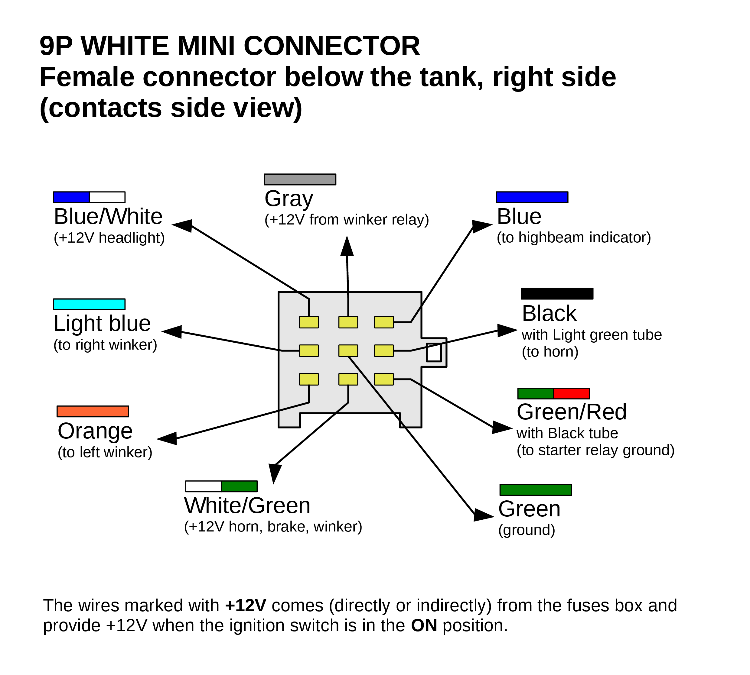
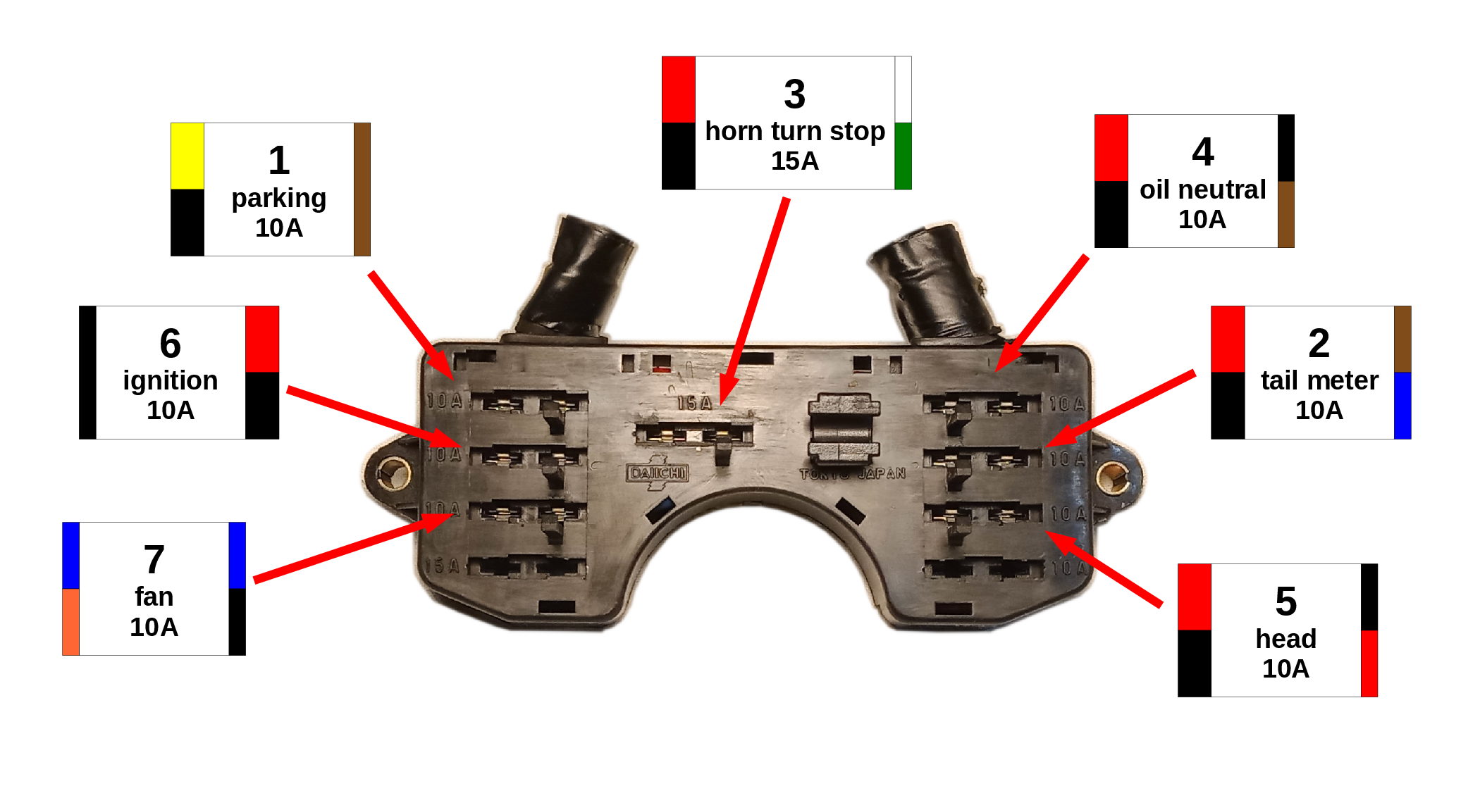
Connectors wires color
Il diodo del circuito di sicurezza dell'avviamento (starter interlock)
 A cosa serve il diodo presente nell'impianto elettrico della Honda NTV650 Revere (codice OEM 31700124008) e presente anche in altri modelli? Nel catalogo ricambi Honda il componente è identificato fome rectifier ma si tratta a tutti gli effetti di un singolo diodo e viene correttamente identificato come tale nello schema elettrico. Alcuni venditori di ricambi lo etichettano addirittura come regolatore di tensione o baggianate simili.
La moto ha un circuito di sicurezza per l'avviamento per cui è possibile azionare il motorino di avviamento solo se il cambio è in folle oppure se la leva della frizione è tirata e il cavalleto laterale è alzato.
Per ottenere questo la linea del negativo del relé di avviamento è collegata effettivamente a massa solo se si verifica almeno una di queste due condizioni indipendenti:
- Cambio in folle (interruttore della folle chiuso verso massa).
- Leva frizione tirata e cavalletto laterale alzato (entrambi gli interruttori chiusi verso massa).
Tuttavia la spia della folle deve accendersi solo nella prima condizione. Il diodo quindi separa la spia e l'interruttore della folle dagli altri due interruttori (frizione e cavalletto). La spia della folle troverà pertanto la via verso massa solo nel caso di interruttore folle chiuso, ma verrà bloccata dal diodo e non vedrà la massa eventualmente raggiungibile tramite gli interruttori di frizione e cavalletto chiusi.
Riferimenti web
- kojaycat.co.uk - Rivenditore di connettori, anche marchio Sumitomo.