Table of Contents
Vector Welding MIG 130A
Welding machine MIG 130A by Vector Welding - The Missing Manual

I purchased this welding machine for €146 (January 2025) on the Amazon website. The welding machine is sold by Vector Welding, based in Germany and is shipped from that country in a few days. The kit I purchased is ideal for beginners as it includes not only the continuous wire welder, but also a spool of flux-cored wire and an auto-darkening protective helmet.
This is a really interesting kit for the beginner hobbyist. The amperage limited to 130 A still allows you to easily weld sheets of up to 5 ~ 6 mm thick, but above all it allows you to use the device connected to a 3 kW home electrical system. It is not possible to weld with shielding gas, but the use of flux-cored wire is still a widely used technique that allows good results to be obtained.
In my opinion, the presence of an auto-darkening helmet is to be considered essential for the beginner: using a mask to raise and lower manually every time you start welding would add a significant level of difficulty, which is instead completely resolved with this accessory.
What I think you should buy right away to do your first experiments are a pair of welding gloves and a spool of 0.8 mm wire with its nozzle. In fact, experimenting with 1.0 mm wire on thin sheets (1 ~ 2 mm) is not recommended because the possibility of piercing the workpiece with the arc is very high.
The only sore point of the kit is the manual! Only a concise manual in German is provided, the content is poorly edited and sometimes contains information not pertinent to the model in question, being evidently produced with hasty copy and paste from the manual of other models. On the Vector Welding website or elsewhere on the internet there is no downloadable manual for the MIG 130 model. I translated the German version into English, using online tools and proceeded to integrate and improve it with other information found in other manuals online. Below is the result of my work.
Operating Instructions

Intelligent welding machine with digital display
Model number: MIG 130
WARNING
PROTECT YOURSELF AND OTHERS FROM THE RISK OF SERIOUS INJURY OR DEATH. KEEP CHILDREN AWAY FROM THE WORK AREA. PACEMAKER USERS SHOULD AVOID THE WORK AREA AND CONSULT A DOCTOR BEFOREHAND. DO NOT DISCARD OR MISPLACE THESE INSTRUCTIONS. CAREFULLY READ THE OPERATOR'S MANUAL BEFORE INSTALLING, OPERATING, OR MAINTAINING THE EQUIPMENT.
Welding equipment and processes can cause serious injury, death, or damage to equipment or property if the user does not strictly adhere to safety regulations and take necessary precautions.
Safe practices have evolved from past experience with welding and cutting. These practices must be learned through study and training before using the equipment. Some practices apply to equipment connected to power lines, while others are specific to engine-driven equipment. Anyone without extensive training in welding and cutting should not attempt to weld.
Safe practices are outlined in the European Standard EN60974-1, titled: Safety in Welding and Allied Processes, Part 2: Electrical. ALL INSTALLATION, OPERATION, MAINTENANCE, AND REPAIR WORK SHOULD BE PERFORMED ONLY BY QUALIFIED PERSONNEL.
1.1 Damage caused by arc welding
![]() WARNING Electric shock can kill
WARNING Electric shock can kill
Touching live electrical components can result in fatal shocks or severe burns. The electrode and work circuit remain electrically live whenever the output is active. Additionally, the input power circuit and internal machine circuits are live when the power is on. In semi-automatic or automatic wire welding, the wire, wire reel, drive roll housing, and all metal parts in contact with the welding wire are also electrically live. Improperly installed or inadequately grounded equipment poses a serious hazard.
- Do not touch live electrical parts.
- Wear dry, hole-free insulating gloves and body protection.
- Insulate yourself from work and ground using dry insulating mats or covers.
- Disconnect input power or stop engine before installing or servicing this equipment. Lock input power disconnect switch open, or remove line fuses so power cannot be turned on accidentally.
- Properly install and ground this equipment according to its Owner’s Manual.
![]() WARNING Arc rays can burn eyes and skin, noise can damage hearing
WARNING Arc rays can burn eyes and skin, noise can damage hearing
Arc rays from the welding process produce intense heat and strong ultraviolet rays that can burn eyes and skin. Noise from some processes can damage hearing.
- Wear a welding helmet fitted with a proper shade of filter to protect your face and eyes when welding or watching.
- Wear approved safety glasses. Side shields recommended.
- Use protective screens or barriers to protect others from flash and glare; warn others not to watch the arc.
- Wear protective clothing made from durable, flame-resistant material(wool and leather) and foot protection.
- Use approved ear plugs or ear muffs if noise level is high.
- Never wear contact lenses while welding.
![]() WARNING Fumes and gases can be hazardous to your health
WARNING Fumes and gases can be hazardous to your health
Welding produces fumes and gases. Breathing these fumes and gases can be hazardous to your health.
- Keep your head out of the fumes. Do not breathe the fumes.
- If inside, ventilate the area and/or use exhaust at the arc to remove welding fumes and gases.
- If ventilation is poor, use an approved air-supplied respirator.
- Work in a confined space only if it is well ventilated, or while wearing an air-supplied respirator. Shielding gases used for welding can displace air causing injury or death. Be sure the breathing air is safe.
- Do not weld in locations near degreasing, cleaning, or spraying operations. The heat and rays of the arc can react with vapours to form highly toxic and irritating gases.
- Do not weld on coated metals, such as galvanized, lead, or cadmium plated steel, unless the coating is removed from the weld area, the area is well ventilated, and if necessary, while wearing an air- supplied respirator. The coatings and any metals containing these elements can give off toxic fumes if welded.
![]() WARNING Welding can cause fire or explosion
WARNING Welding can cause fire or explosion
Sparks and spatter fly off from the welding arc. The fly sparks and hot metal, weld spatter, hot workpiece, and hot equipment can cause fires and burns. Accidental contact of electrode or welding wire to metal objects can cause sparks, overheating, or fire.
- Protect yourself and others from flying sparks and hot metal.
- Do not weld where flying sparks can strike flammable material.
- Remove all flammables far away from the welding arc. If this is not possible, tightly cover them with approved covers.
- Be alert that welding sparks and hot materials from welding can easily go through small cracks and openings to adjacent areas.
- Watch for fire, and keep a fire extinguisher nearby.
- Be aware that welding on a ceiling, floor, bulkhead, or partition can cause fire on the hidden side.
- Do not weld on closed containers such as tanks or drums.
- Connect work cable to the work as close to the welding area as practical to prevent welding current from travelling long, possibly unknown paths and causing electric shock and fire hazards.
- Do not use welder to thaw frozen pipes.
- Remove stick electrode from holder or cut off welding wire at contact tip when not in use.
![]() WARNING Flying sparks and hot metal can cause injury
WARNING Flying sparks and hot metal can cause injury
Chipping and grinding cause flying metal. As welds cool, they can throw off slag.
- Wear approved face shield or safety goggles. Side shields recommended.
- Wear proper body protection to protect skin.
![]() WARNING Cylinders can explode if damaged
WARNING Cylinders can explode if damaged
Shielding gas cylinders contain gas under high pressure. If damaged, a cylinder can explode. Since gas cylinders are normally part of the welding process, be sure to treat them carefully.
- Protect compressed gas cylinders from excessive heat, mechanical shocks, and arcs.
- Install and secure cylinders in an upright position by chaining them to a stationary support or equipment cylinder rack to prevent falling or tipping.
- Keep cylinders away from any welding or other electrical circuits.
- Never allow a welding electrode to touch any cylinder.
- Use only correct shielding gas cylinders, regulators, hoses, and fittings designed for the specific application; maintain them and associated parts in good condition.
- Turn face away from valve outlet when opening cylinder valve.
- Keep protective cap in place over valve except when cylinder is in use or connected for use.
- Read and follow instructions on compressed gas cylinders, associated equipment.
![]() WARNING Engine fuel can cause fire or explosion
WARNING Engine fuel can cause fire or explosion
Engine fuel is highly flammable.
- Stop engine before checking or adding fuel.
- Do not add fuel while smoking or if unit is near any sparks or open flames.
- Allow engine to cool before fuelling. If possible,check and add fuel to cold engine before beginning job.
- Do not overfill tank — allow room for fuel to expand.
- Do not spill fuel. If fuelling is spilled, clean up before starting engine.
![]() WARNING Moving parts can cause injury
WARNING Moving parts can cause injury
Moving parts, such as fans, rotors, and belts can cut fingers and hands and catch loose clothing.
- Keep all doors, panels, covers, and guards closed and securely in place.
- Stop engine before installing or connecting unit.
- Have only qualified people remove guards or covers for maintenance and troubleshooting as necessary.
- To prevent accidental starting during servicing, disconnect negative (-) battery cable from battery.
- Keep hands, hair, loose clothing, and tools away from moving parts.
- Reinstall panels or guards and close doors when servicing is finished and before starting engine.
![]() WARNING Sparks can cause battery gases to explode; battery acid can burn eyes and skin
WARNING Sparks can cause battery gases to explode; battery acid can burn eyes and skin
Batteries contain acid and generate explosive gases.
- Always wear a face shield when working on a battery.
- Stop engine before disconnecting or connecting battery cables.
- Do not allow tools to cause sparks when working on a battery.
- Do not use welder to charge batteries or jump start vehicles.
- Observe correct polarity (+ and –) on batteries.
![]() WARNING Steam and pressurized hot coolant can burn face, eyes, and skin
WARNING Steam and pressurized hot coolant can burn face, eyes, and skin
The coolant in the radiator can be very hot and under pressure.
- Do not remove radiator cap when engine is hot. Allow engine to cool.
- Wear gloves and put a rag over cap area when removing cap.
- Allow pressure to escape before completely removing cap.
1.2 Effects of low frequency electric and magnetic fields
Electric current flowing through any conductor generates localized electric and magnetic fields (EMF). The discussion about the effects of EMF is ongoing worldwide. So far, there is no concrete evidence proving that EMF has adverse effects on health. However, research on potential harm caused by EMF is still underway. Until a definitive conclusion is reached, we should minimize exposure to EMF as much as possible.
To reduce magnetic fields in the workplace, use the following procedures:
- Keep cables close together by twisting or taping them.
- Arrange cables to one side and away from the operator.
- Do not coil or drape cable around the body.
- Keep welding Power Source and cables as far away from body as practical.
- The people with heart-pacemaker should be away from the welding area.
1.3 Symbol chart
| | On |
| | Off |
| | Dangerous voltage |
| | Increase/Decrease |
| | Circuit Breaker |
| | AC Auxiliary Power |
| | Fuse |
| | Amperage |
| | Voltage |
| | Hertz |
| | Frequency |
| | Negative |
| | Positive |
| | Direct Current (DC) |
| | Protective Earth (Ground) |
| | Line |
| | Line Connection |
| | Auxiliary Power |
| | Receptacle Rating-Auxiliary Power |
| | Single Phase |
| | Three Phase |
| | Three Phase Static Frequency Converter - Transformer - Rectifier |
| | Remote |
| | Duty Cycle |
| | Percentage |
| | Panel/Local |
| | Shielded Metal Arc Welding (SMAW) |
| | Gas Metal Arc Welding (GMAW) |
| | Gas Tungsten Arc Welding (GTAW) |
| | Air Carbon Arc Cutting (CAC-A) |
| | Constant Current |
| | Constant Voltage or Constant Potential |
| | High Temperature |
| | Fault Indication |
| | Arc Force |
| | Touch Start (GTAW) |
| | Variable Inductance |
| | Voltage Input |
| | Wire Feed Function |
| | Wire Feed Towards Workpiece With Output Voltage Off |
| | Welding Gun |
| | Purging of Gas |
| | Continous Weld Mode |
| | Spot Weld Mode |
| | Spot Time |
| | Preflow Time |
| | Postflow Time |
| | Two Step Trigger Operation Press to initiate wirefeed and welding, relase to stop. |
| | Four Step Trigger Operation Press and hold for preflow, relase to start arc. Press to stop arc, hold for postflow. |
| | Burnback Time |
| | Inches per Minute |
| | Meters per Minute |
| | See Note |
| | See Disposal Note |
| | Pulse Welding |
2.1 Brief introduction
MIG130 Welding Machine: Lightweight, efficient, and energy-saving, designed for continuous and durable performance. It features IGBT inverter technology and an advanced design that enhances energy efficiency and reduces power consumption. The efficient feedback control circuit ensures excellent dynamic response. Equipped with an automatic arc length compensation function, it provides a stable arc with minimal spatter and smooth welds, making it particularly suitable for thin plate welding. We welcome individuals from all sectors to use our products and offer valuable feedback. We are committed to continuously improving the quality of our products and services.
2.2 Working principle
The operational process of MIG welding machines is illustrated in the figure below. For instance, single-phase 230V AC is first rectified into DC (approximately 312V), then converted into medium-frequency AC (around 20-40kHz) by the inverter device (IGBT module). After voltage reduction by the medium-frequency converter (main transformer) and rectification through the medium-frequency rectifier (fast recovery diodes), DC is output by the IGBT module. The circuit utilizes current feedback control technology to ensure stable current output. Additionally, the welding current parameter can be continuously and smoothly adjusted to meet the specific requirements of the welding machine.

2.3 Duty cycle
The rated operating efficiency (duty cycle) of a welding power source refers to the amount of time it can operate at its specified welding current without exceeding the temperature limits of its components' insulation. To illustrate a 10-minute duty cycle, consider the following example. If a welding power source is designed for a 60% duty cycle, operating at 130 amps and 20.0 volts, it means the machine is built to deliver the rated current (130A) for 6 minutes, which represents the welding time, within each 10-minute period (60% of 10 minutes equals 6 minutes). For the remaining 4 minutes of the 10-minute period, the welding power source must operate at idle to allow it to cool down.

2.4 Specifications
| Model | MIG130 |
|---|---|
| Weight | 4 kg |
| Dimensions | 340 x 140 x 170 mm |
| Cooling System | Fan-cooled |
| Welder type | Multi Process Inverter Power Source |
| European Standards | EN 60974-1 / IEC 60974-1 |
| Mains voltage | 1 x 230 Volt + 15% |
| Grid frequency | 50/60Hz |
| Wire roll weight | 0.5 kg / 1 kg |
| Wire diameter | ø 0.8 / ø 1.0 |
| Welding Current (MIG) | 40-130A |
| Welding Current (ARC) | 20-120A |
| Effective Input Current | 14.4 A |
| Max Input Current | 18.7 A |
| Duty cycle (ED) MIG 40°C | 130A@60%20.5V, 101A@100%19V |
| Duty cycle (ED) ARC 40°C | 120A@ 60%24.8V, 95A@100%23.8V |
| Efficiency | 80% |
| Power Factor | 0.93 |
| Rated working voltage (V) | 20 |
| Rated input capacity (KVA) | 3.1 |
| No load loss (W) | 40 |
| Open Circuit Voltage | 62 V DC |
| Protection Class | IP23 |
| Insulation Class | H |
NOTE
- Use RMS current to determine the appropriate cable size and specifications.
- Ensure that generator requirements align with the maximum cycle power and duty cycle.
- Motor current ratings and thermal switches are recommended for proper operation. Check local regulations for specific requirements.
Due to variations, the power, voltage, ratings, capacities, measurements, dimensions, and weights of manufactured products are approximate values. Actual performance depends on proper installation, usage, application, maintenance, and servicing.
2.5 Included items
- MIG welding torch (1.5 m) MB-14AK.
- 200 ampere welding cable (2 m) with electrode holder.
- 300 ampere earth cable (2 m).
- Auto darkening welding helmet.
- Hammer brush.
- 0.5 kg spool of flux-cored wire 1.0 mm for no-gas welding.
- Operating instructions.
2.6 Current and voltage ranges
Using the Vector Welding MIG 130A machine in FCAW mode you can adjust the current (ampere) from a mimimum of 30 A to the maximum of 130 A. Once selected the current, you can adjust also the voltage, to control the shape of the arc. The selectable voltage range depends upon the selected current and the wire diameter; in the following table you can see the voltage range available for the lower and the higher current selectable.
| FCAW Mode | ||
|---|---|---|
| Wire diameter | 1.0 mm | |
| Current (ampere) | Min 50 | Max 130 |
| Voltage range (volt) | 15.1 ~ 20.0 | 17.1 ~ 20.0 |
| Wire diameter | 0.8 mm | |
| Current (ampere) | Min 30 | Max 130 |
| Voltage range (volt) | 12.1 ~ 17.0 | 17.1 ~ 20.0 |
3.1 Control panel layout

| 1 | Welding mode | Press to select one of the FCAW/MMA welding modes. |
|---|---|---|
| 2 | Welding parameters setting | Press the knob to select which parameter you want to adjust: Current or Voltage / Thermal arc current. Rotate the knob to adjust the selected welding parameter. |
| 3 | Wire diameter / Self-locking welding | Press to select the appropriate diameter of the welding wire to be used. Press the button for three seconds to enable or disable self-locking welding. |
| 4 | Negative connector | The welding current flows from the power source via high-power connectors with bayonet locking. Care must be taken to ensure that the plug is inserted and tightened to ensure a good electrical connection. |
| 5 | Positive connector | The welding current flows from the power source via high-power connectors with bayonet locking. It is important to ensure that the plug is inserted and tightened to ensure a good electrical connection. |
| 6 | 2-pin control socket | The 2-pin socket is used to connect the torch switch to the welding power supply circuit. |
LED and Digital Display
| Symbol | Symbol Name | Use / Eplanation |
|---|---|---|
| | Input voltage | Input power indicator. When it is lit it means that the device is turned on. |
| | Cooling fan | The device is air-cooled. |
| | Overheating and/or failure | This indicator lights up when the device is in an abnormal state, such as overheating or overcurrent. Error message: When an “EU/EH/EO” error code appears on the screen, it means that the device is in an error state. |
| | Current | When this indicator is on, you can adjust the welding current (ampere). Presso knob 2 to select the ampere parameter and turn it to adjust. |
| | Voltage / Thermal arc current | When this indicator is on, you can adjust the following: Voltage (FCAW mode): adjust the welding voltage. Thermal arc current (MMA mode): adjust the welding current. Presso knob 2 to select the voltage parameter and turn it to adjust. |
| | Wire diameter | Press button 3 to select the correct parameter, based on the wire used. |
| | Self-locking welding | When this indicator is on, the self-locking welding mode is enabled. Press and release the torch switch once to start welding, press and release again to stop it. Keep button 3 pressed for three seconds to toggle the self-locking welding mode. |
| | FCAW Mode | When this indicator is on, the FCAW welding mode is selected. This mode requires a continuously-fed consumable tubular wire electrode containing a flux. Using a flux-cored wire, a protecting gas is not required (no-gas welding). Press button 1 to toggle the welding mode. |
| | MMA Welding | When this indicator is on, the MMA welding mode is selected (stick welding). This mode uses a consumable stick electrode covered with a flux to lay the weld. Press button 1 to toggle the welding mode. |
3.2 Installing the wire spool
Installation of the wire spool:
- Unscrew the fixing pin from the hub.
- Place the spool onto the hub and screw the fixing pin back. Turn securely to keep the wire spool stable on the hub.
 CAUTION
Be careful with the wound wire as it may unwind once it is released from the spool. Hold the end ofthe wire firmly and do not let it go.

3.3 Inserting the wire into the feed mechanism
WARNING
Electric shock is fatal! Make sure the input power is disconnected from the power source before you proceed. Do not reconnect the input power to the power source unless instructed to do so by the instructions below.
- If necessary, loosen the spring pressure adjustment lever. Then swing it down.
- Move the pressure roller arm (top) by pushing it to the right.
- Make sure the wire end is free of burrs and bends. Thread it through the input wire guide and over the feed roller. Make sure you use the appropriate notch.
- Feed the MIG wire over the drive roller, through the output wire guide and past the MIG torch adapter. Then adjust the MIG torch to ensure that the MIG wire feeds into the torch barrel.
- Close the pressure roller arm.
- Return the spring pressure adjustment lever to its original position.
- Use the spring pressure adjustment lever to create a correct condition (clockwise to tighten and anti-clockwise to loosen).
The last picture shows the wire successfully inserted.

NOTE
When the MIG gun switch is pressed, the wire feed mechanism starts slowly, at the speed determined by the synergic program. If the welding arc does not start, for example because the gun is held away from the workpiece, after a few seconds the wire feed speed is increased to speed up the wire reaching the welding tip. To facilitate the exit of the wire from the MIG gun, it may be useful to temporarily remove the nozzle and the welding tip.
3.4 Feed roller pressure adjustment
The roller on the swing arm applies pressure to the grooved roller via an adjustable tension device. The tension adjuster should be set to the minimum pressure that will provide satisfactory wire feed without slippage. If slipping occurs, and inspection of the wire out of the MIG Gun reveals no deformation or wear, the conduit liner should be checked for kinks or clogging from metal flakes. If this is not the cause of slipping, the feed roll pressure can be increased by rotating the tension adjusting knob clockwise. The use of excessive pressure may cause rapid wear of the feed roller, motor shaft and motor bearings.
NOTE
Genuine contact tips and liners should be used. Many non-genuine liners use inferior materials which can cause wire feed problems.
3.5 Changing the feed roller
Feed rollers often come with a rust protective coating that needs to be cleaned off before installation. A feed roller has two different sized grooves. The stamped marking on the feed roller refers to the groove furthest from the stamped marking.

The size that is visible when the feed roller is fitted, is the size of the groove in use.
To remove the feed roller, rotate the bracket cover and match the bracket knob splines to those on the drive gear. To install feed rollers, place them in the drive gear splines and rotate the cover back on so the splines rest against the face of the drive gear and a click is heard.


NOTE
All feed rollers have their wire size stamped on the side of the roller. For rollers with different sized grooves, the outer (visible when roller is installed) stamped wire size is the one in use. When selecting and ordering feed roller kits, refer to the appendix to select the correct one. The kit includes work rollers, an input wire guide and an output wire guide for a specific wire type and size.
WARNING
The welding wire becomes hot when it is fed with current by pressing the MIG welding torch switch. When the electrode and the workpiece come into contact, an arc is created by pressing the MIG welding torch switch.
3.6 Configuration for MIG welding gasless wire (FCAW)
This welding machine has a supply voltage compensation function. When the supply voltage fluctuates within 15% of the rated voltage, the machine can continue to operate normally without affecting its operation.
When using a longer cable, it is recommended to use a cable with a larger cross-section to reduce voltage drops; if the connecting cable is too long, it may affect the operation of the arc and other functions of the machine, such as weakening the high frequency arc ignition performance or causing the system to not work properly. For this reason, we recommend that you use the accessories provided to ensure that the machine works properly.
- Check that the vent holes of the welding machine are not covered and blocked to avoid failure of the cooling system.
- Reliably ground the chassis with a conductive cross-section area of at least 4 mm2 by connecting it to the grounding device at the connection screw from the back of the welding machine or by ensuring that the grounding end of the power socket is reliably grounded separately. To ensure safety, you can also use the two methods at the same time.
- Connect the grounding wire to the positive connector, according to the diagram.
WARNING
Before connecting the work clamp to the work, make sure the power is off.
CONNECTIONS
Loose screw terminal connections can cause overheating and will cause the connector to melt into the clamp. Remove all packing materials before use. DO NOT block the ventilation slots on the front or back of the welding power source.
NOTES
Depending on the type of welding mode you are using, you may need to switch the cable polarity. Follow the manufacturer's recommendations.

This completes the installation of the welding machine, which is ready for welding.
3.7 Configuration for stick metal arc welding (MMA)
WARNING
Before welding, make sure all appropriate and recommended safety precautions are in place.
NOTE
The following configuration is known as DC electrode positive welding or reverse polarity welding. Please contact the STICK electrode manufacturer for more information and polarity recommendations.
- Turn the power switch (located on the rear panel) to OFF.
- Connect the work cable and the STICK as shown in the figure.
- Set the welding mode to MMA (STICK).
- Set the welding current to the desired amperage with the control knob.
- Install the stick electrode into the electrode holder.
- Now you can start STICK welding.
NOTE
To weld, sweep the electrode across the workpiece to create an arc and move it slowly along the work piece at a constant arc length.

3.8 Working environment
- Altitude above mean sea level less than 1000 m.
- Working temperature range: -10 °C ~ +40 °C.
- Relative humidity less than 90% (20 °C).
- It is preferable to place the machine on a flat surface, the maximum angle must not exceed 15°.
- The content of dust, acids, corrosive gases in the ambient air or substance may not meet normal applicable standards.
- Make sure that there is sufficient ventilation during welding. There must be at least 30 cm free space between the machine and the wall.
3.9 Working instructions
- Read section 1 carefully before using this equipment.
- Connect the ground clamp directly to the machine.
- When closing the power switch, the open circuit voltage may flow. Do not touch the output electrode with any part of your body.
- When starting the work, no unauthorized people should be present. Do not look into the arc with unprotected eyes.
- Make sure the machines are well ventilated to improve the running rate.
- Turn off the machine when the work is finished to save energy.
- If the power switch is turned off by an error, do not restart the mechine until the problem is solved. Otherwise, further problems will arise.
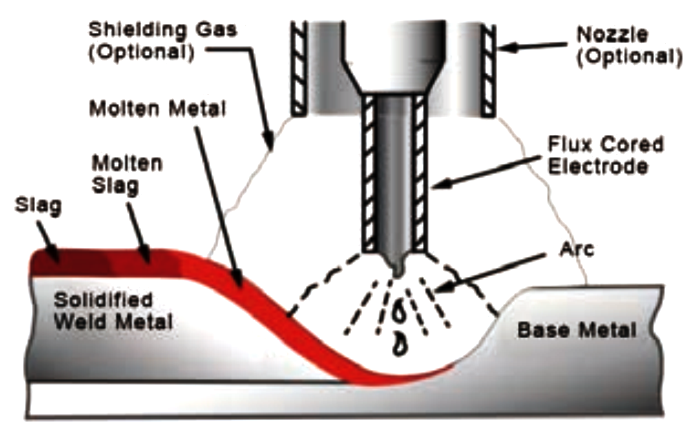
4.1 MIG (FCAW) welding technique basics
This paragraph explains the fundamental principles of MIG welding. In this process, a MIG welding torch is held by hand, feeding the electrode (welding wire) into the weld pool while an electric arc generates heat. The arc is shielded by a protective gas or a gas mixture to prevent contamination.
Flux-Cored Arc Welding (FCAW) is an electric welding process that joins metal parts by generating heat through an arc between the continuously fed electrode wire and the workpiece. The flux inside the tubular wire decomposes to provide protection, with additional shielding possibly supplied by an external gas or gas mixture. This process is typically semi-automatic but can also be fully automated or machine-controlled. FCAW is commonly used for welding large-diameter electrodes in flat or horizontal positions. However, it is less frequently applied to stainless steel welding and overlapping joints.
Position of the MIG welder gun
The angle of the MIG welder to the workpiece affects the width of the weld. The MIG welder should be held at an angle to the weld joint. (See figure below). Hold the MIG gun in a way that allows continuous visibility of the welding seam. Always wear a welding helmet with the appropriate filter lenses and use the proper safety equipment.
Pulling (moving backhand) is the way to go if you use flux-cored wire. This method prevents slag inclusions, where the flux gets trapped in the molten metal, which leaves an ugly, rough, and porous weld. The welding gun must be angled at about 15° towards the direction of travel, this helps push the slag away from the melting pool. Increasing the travel angle over 20 degrees can cause more spatter with inconsistent arc.


WARNING
DO NOT pull back on the MIG gun when the arc is present. This will cause excessive wire extension (stick out) and results in a poorer weld. The electrode wire is not energized until the MIG gun switch is pressed, so the wire can be placed on the seam or joint before the lowering the helmet.
Best technique recommendation
For most FCAW applications, the drag (pull) technique is best, especially in flat and horizontal welding. For vertical welding, use the vertical uphill technique for stronger welds.
Push vs. drag (pull) technique
- Drag (pull) technique (recommended for FCAW)
- The gun is angled 10-15° back, pulling the weld pool behind.
- Produces deeper penetration, making it ideal for structural and thick materials.
- Preferred for flat, horizontal, and overhead positions.
- Push technique (less common for FCAW)
- The gun is angled forward (pushing the weld pool ahead).
- Results in shallower penetration but a wider bead.
- Less effective in FCAW since slag can interfere with the weld.
Vertical welding (uphill vs. downhill)
- Vertical uphill (bottom to top) (recommended for FCAW)
- Used for thicker materials (1/4 inch or more).
- Produces stronger welds with good penetration.
- Requires a slight weaving motion to control the weld pool and avoid excessive buildup.
- Vertical downhill (top to bottom) (not common for FCAW)
Welding progress speed
The speed at which the melt pool moves determines the width of the weld seam and the depth of penetration.
Distance of the MIG nozzle to the workpiece
The electrode wire should protrude from the nozzle by about 10-20 mm (3/8“ - 3/4”). The distance may vary depending on the type of joint.
Establishing the arc and weld bead creation
Before welding on the finished workpiece, it is recommended to make a test run on a sample of the same material. The easiest welding method for MIG beginners is the flat position. The equipment can be used for flat, overhead and vertical welding.
To practice MIG welding, join some pieces of mild steel plate 150 mm x 150 mm (6“ x 6”), with thickness of 1.6 mm or 5.0 mm (1/16“ or 3/16”). Use 0.9 mm (0.35“) flux cored wire.
Adjusting the power source
The Vector Welding MIG 130A system has two settings that must be balanced: the welding current (ampere) and the welding voltage; this requires some practice by the operator. Another important welding paramter is the wire feed speed: the MIG 130A automatically adjusts the wire feed speed according to the wire diameter and the current selected. Increasing the current also increases the wire feed speed.
Increasing the welding voltage does not significantly change the current, but it does allow the welding arc to be lengthened. Decreasing the voltage results in a shorter arc.
If the wire speed is high and the welding voltage is low (short arc), “stubbing” may occur because the wire dips into the molten pool and does not melt. Welding in these conditions normally produces a poor weld due to lack of fusion. If, on the contrary, the welding voltage is too high (longer arc), large drops will form on the end of the wire, causing spatter.
The correct wire speed and current settings can be seen by the shape of the weld metal and heard as a smooth arc.
4.2 Choosing the welding wire diameter
0.8 mm wire diameter
Using a 0.8 mm wire diameter with a synergic FCAW (Flux-Cored Arc Welding) machine, is generally suggested when welding 1 ~ 3 mm (0.04 ~ 0.12 inch) thick steel sheets. In this cases you need a low heat input to avoid burn-through. Here are the recommended settings:
- Recommended FCAW Synergic Settings for 1 mm Steel
- Wire Diameter: 0.8 mm (0.030 inch) flux-cored wire (smaller diameter preferred for thin sheet metal).
- Amperage: 40-70A (the machine will adjust based on wire feed speed).
- Voltage: 15-17V (short arc to control heat input).
- Wire Feed Speed: Automatically adjusted by the synergic control, but generally 3-5 m/min (120-200 in/min).
- Shielding Gas (if using gas-shielded FCAW): 75% Argon / 25% CO₂ for smooth arc and minimal spatter.
- Travel Speed: Keep it fast to prevent excessive heat buildup.
- Tips to Avoid Burn-Through & Warping
- Use a pulsed or stitch welding technique to minimize heat input.
- Keep torch angle at 10-15° for better control.
- Use backing material (like copper or aluminum) to help dissipate heat.
- Practice on scrap material to fine-tune settings.
1.0 mm wire diameter
Using a 1.0 mm wire diameter in FCAW is generally suggested when welding thicker base metals or when a higher deposition rate is needed. A 1.0 mm wire with a current of 130 ampere can weld a workpiece of 6.0 mm thickness. Here are some typical scenarios:
- Thicker Materials
- When welding steel in the range of approximately 3 mm or greater, a 1.0 mm wire is often preferred. The larger diameter supports higher welding currents, which provide deeper penetration and stronger welds for thicker materials.
- High Deposition Applications
- In production environments or heavy fabrication where faster metal deposition is required to build up welds quickly, the 1.0 mm wire enables a higher deposition rate without needing additional passes.
- Structural and Heavy-Duty Welding
- For structural applications or heavy-duty jobs - such as welding components for construction or heavy equipment - the increased weld metal output and robust bead formation with a 1.0 mm wire make it a suitable choice.
Remember that the specific settings (current, voltage, travel speed) will be adjusted by your synergic welding machine based on the selected program, so it’s important to refer to the manufacturer’s guidelines and conduct test welds for optimal performance.
4.3 FCAW amperage guide for steel thickness
This is a reference table reported into the Flameweld MTA1650 welding machine:

| Flux-cored wire diameter 0.8 mm | ||
|---|---|---|
| Steel thickness | Ampere | Volt |
| 1 mm | 50 | 16.5 |
| 2 mm | 70 | 17.5 |
| 3 mm | 90 | 18.5 |
| 4 mm | 110 | 19.5 |
| 5 mm | 125 | 20.3 |
| 6 mm | 140 | 21.0 |
| 7 mm | 160 | > 22.0 |
This is a generic reference table from vector-welding.it site, it does not mention voltage, which is however a determining parameter:
| Steel thickness | Ampere |
|---|---|
| 0.8 mm | 30 |
| 1.0 mm | 50 |
| 2.0 mm | 90 |
| 3.0 mm | 125 |
| 4.0 mm | 140 |
4.4 Voltage adjustment
Voltage adjustment in gas-less FCAW (self-shielded flux-cored welding) plays a crucial role in controlling the arc characteristics, heat input, and overall weld quality. Here’s a deeper look at how voltage adjustment affects the process.
Bead on plate welds have increased bead width and dilution as the arc voltage increases, although the depth of penetration is relatively unaffected:

In a prepared V-butt joint, increasing the arc voltage may lead to lack of fusion in the root as the wide arc will not reach the bottom of the root. In this case, a somewhat counterintuitive effect is that reducing the voltage will increase the depth of penetration as the narrow arc column is more easily able to reach the bottom of the preparation:

1. Arc Length and Stability
- Shorter Arc (Lower Voltage):
- A lower voltage setting produces a shorter, more concentrated arc. This results in a tighter, more stable arc that provides deeper penetration in a localized area. However, if the voltage is too low, the arc can become “stiff” or even cause the electrode to stick, leading to potential undercut or lack of fusion.
- Longer Arc (Higher Voltage):
- Increasing the voltage lengthens the arc. A longer arc distributes the heat over a wider area, which tends to produce a flatter bead profile with less penetration. Excessive voltage, however, may result in increased spatter and less consistent arc behavior.
2. Impact on Weld Bead Geometry and Penetration
- Bead Shape:
- Lower Voltage: Tends to create a narrower, more convex bead due to the concentrated heat.
- Higher Voltage: Often results in a flatter and wider bead with less pronounced reinforcement.
- Penetration:
- With lower voltage, the concentrated energy produces deeper penetration, which is desirable for thicker sections. Conversely, higher voltage spreads the energy over a larger area, reducing penetration — beneficial when working on thinner materials to avoid burn-through.
3. Effects on Spatter and Slag Formation
- Spatter:
- In gas-less FCAW, managing spatter is critical because the flux not only shields the weld but also forms slag to protect it. Too high a voltage can destabilize the arc, increasing spatter and potentially affecting slag quality.
- Slag Formation:
- Proper voltage ensures the flux melts uniformly, forming a consistent slag cover that protects the weld during cooling. If the voltage is not optimal, improper slag formation might lead to weld defects and difficulties in post-weld cleaning.
4. Interaction with Other Parameters
- Wire Feed Speed and Current:
- In synergic systems, voltage is part of an interdependent set of parameters. While the machine often automatically adjusts the voltage in relation to the set wire feed speed and current, understanding its role helps in fine-tuning for specific applications.
- Flux Composition:
- Different flux formulations in the wire require different voltage settings to ensure proper deoxidation and protection. Adjusting voltage is critical to match the characteristics of the flux-cored wire being used.
5. Practical Considerations
- Application-Specific Adjustments:
- For thinner materials, a slightly lower voltage may be chosen to concentrate heat and avoid excessive spread.
- For thicker materials or when a wider bead is needed, a higher voltage setting can help distribute heat more evenly.
- Trial and Testing:
- Although synergic machines come with preset programs, welders often perform test welds to fine-tune the voltage (alongside current and wire speed) to achieve the best balance between penetration, bead shape, and minimal spatter.
In summary, voltage adjustment in gas-less FCAW with flux-cored wire is pivotal in defining the arc length and stability, which in turn influences weld bead geometry, penetration, spatter levels, and slag formation. Understanding these interactions allows for better control over the welding process and ultimately a higher quality weld.
4.5 Example weld diagrams and pictures
The following image shows some examples of how welding parameters affect the result. Current (amps, often associated with wire feed speed), voltage, travel speed, contact-tip-to-work distance (CTWD or stick-out).

Current (ampere) faults

")
Voltage (arc lenght) faults

")
Travel speed faults

")
4.6 Consumables
- Wire spool size: 16 x 100 mm diameter (inner x outer) x 44 mm.
- Wire type: The most common designations are E71T-11 and E71T-GS. The -11 is a wire for all positions and multi-pass welding while the -GS is a general standard usually suited for a single pass welding.
- Contact tip: the tip has an M6 thread x 25 mm lenght. The torch consumables (tip and nozzle) should be compatible with the Binzel standard MIG torches MB15, also labeled as AK15 by other manufacturers.
- Nozle: 12 mm inner diameter, 52 mm lenght.
- Tip holder contact: mounting hole: 8 mm female left-hand thread, 41 mm lenght.


5.1 Basic troubleshooting
WARNING
The current in this device is extremely high and therefore dangerous. Do not attempt to open or repair it unless you are a qualified electrical specialist and have undergone intensive training in current measurement strategies and troubleshooting.
If a critical component of the welding machine is faulty, the welding current settings should be checked, and repairs must be performed by an authorized dealer. Basic troubleshooting can be carried out without specialized tools or advanced technical knowledge.
| Ventilation does not work, no welding output available. | 1. Check that the switch is closed. 2. Make sure that the power supply connected to the input line is receiving power. |
|---|---|
| Ventilation works, the power indicator does not light up, no welding output available. | 1. Check whether the various plug cables in the machine are properly plugged-in. 2. Problems with the control circuit, find the cause or contact your dealer. 3. The control cable of the welding torch is broken. 4. The cable of the welding torch is broken. 5. The ground wire is broken or not connected to the welding workpiece. 6. The positive output terminal or the gas-electric output terminal of the torch is disconnected from the connection in the machine. |
| The power indicator is lit, no welding output available. | 1. It may be overheat protection, please turn off the power, wait 2-3 minutes, then turn on the power again to restore normal status. 2. Plug in the power cable of the faulty inverter, keep the power cable of the main transformer unplugged and restart it. If the fault indicator does not light up, the main transformer may be damaged. Measure the primary inductance and Q value (quality factor) of the main transformer with a bridge. 3. It may be that the output rectifier tube is damaged individually, find the same type of rectifier tube and replace it. 4. It may be because of a defective feedback circuit. |
| Insufficient welding current, uncontrolled current regulation. | 1. The secondary line is too long or too thin, shorten the secondary line as much as possible or increase the cross-section. 2. It is also possible that the current control potentiometer is damaged. |
6.1 Maintenance
To ensure that the arc welder works efficiently and safely, it must be serviced regularly. The customer should be advised of maintenance methods and the operation of the welding machine so that he can carry out basic inspections and safety precautions himself and reduce the failure rate as much as possible. The customer can also handle simple repairs and extend the life of the machine himself with the help of these instructions. Maintenance details are recorded in the following table.
WARNING: for safety when maintaining the machine, please switch off the power supply and wait for 5 minutes until the capacity voltage drops to 36V!
| Due period | Maintenance item |
|---|---|
| Daily inspection | Check that the control panel knob on the front and back of the welder is movable and securely mounted. If the knob is not correctly positioned, correct it. If you cannot correct the position of the knob, please replace it immediately. If the switch cannot be moved or placed in the correct position, please replace it immediately; if there are no accessories, please contact the maintenance service. After switching on/off, pay attention to any unusual smells, shaking of the machine or whistling. If any of the above problems exist, find out the origin and fix the problem. If you cannot find the origin of the problem, contact a local representative or branch office. Check that the indicator LEDs are intact, if not, replace the affected LEDs. If the indicator still does not work, replace or service the PCB. Observe the min/max value of the LEDs and compare it with the set value of the LEDs. If this deviates and this has caused changes in the welding process, adjust the values again. Check whether the fan is damaged or can rotate or be controlled normally. If the fan is damaged, replace it immediately. If the fan does not rotate properly, the device can overheat. If something is blocking the fan blades, remove the interference. If the fan still does not rotate after removing the interference, carefully turn the blades towards the fan. If the fan then rotates normally, the starting capacity must be reset. If this is not the case, the entire fan should be replaced. Check whether the quick connector is loose and overheated. If an arc welder has the above problem, you should tighten or change it. Check whether the output cable of the welding current is damaged. If it is damaged, it must be wrapped, insulated or replaced. |
| Monthly inspection | Use dry pressurized air to clean the inside of the machine. Especially for removing dust from the radiator, transformer, inductor, IGBT module, PCB, etc. |
| Monthly check | Check the screws in your arc welder. If they are loose, tighten them. If a screw has slipped, replace it. Remove rust from rusty screws to make sure they work properly. |
| Quarterly inspection | Check if the actual current matches the displayed current. If the values do not match, they should be adjusted. The actual current can be measured by adjusting the plier type ammeter. |
| Annual inspection | Measure the insulated impedance between the main circuit, PCB and the chassis. If it is less than 1M, the insulation seems to be damaged and should be replaced or reinforced. |
Glossary
| GMAW | Gas Metal Arc Welding. A welding process in which an electric arc forms between a consumable wire electrode and the workpiece metals. The arc heats the metals, causing them to melt and join. Along with the wire electrode, a shielding gas feeds through the welding gun, which shields the process from atmospheric contamination. |
|---|---|
| MIG | Metal Inert Gas welding. This kind of GMAW uses inert gases such as argon and helium; mainly used for nonferrous welding. |
| MAG | Metal Active Gas welding. This kind of GMAW uses active gases such as carbon dioxide. Generally used in mixture with argon for steel welding. |
| FCAW | Flux-cored arc welding. |
| SMAW | Shielded Metal Arc Welding. A manual arc welding process that uses a consumable electrode covered with a flux to lay the weld. |
| MMAW | Manual Metal Arc Welding; the same as SMAW. |
| MMA | Manual Metal Arc; the same as SMAW. |
| Stick welding | Informal name for SMAW/MMAW/MMA. |
| Flux | In metallurgy, a flux is a chemical reducing agent. In welding processes, fluxes prevent oxidation of the base and filler materials. The role of flux is typically dual: dissolving the oxides already present on the metal surface to facilitate wetting by molten metal, and acting as an oxygen barrier by coating the hot surface, preventing oxidation. |
| WFS | Wire Feed Speed. |
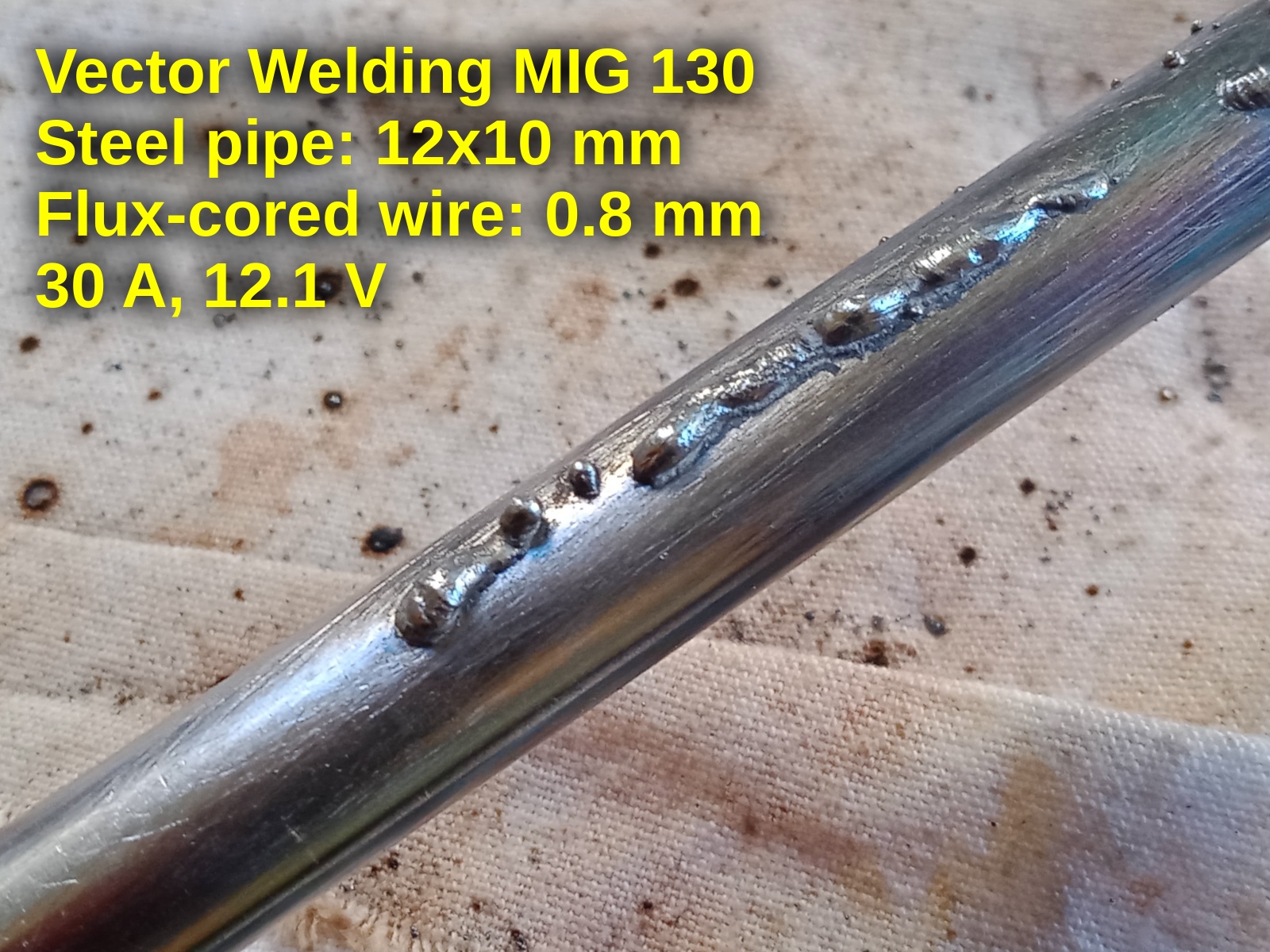
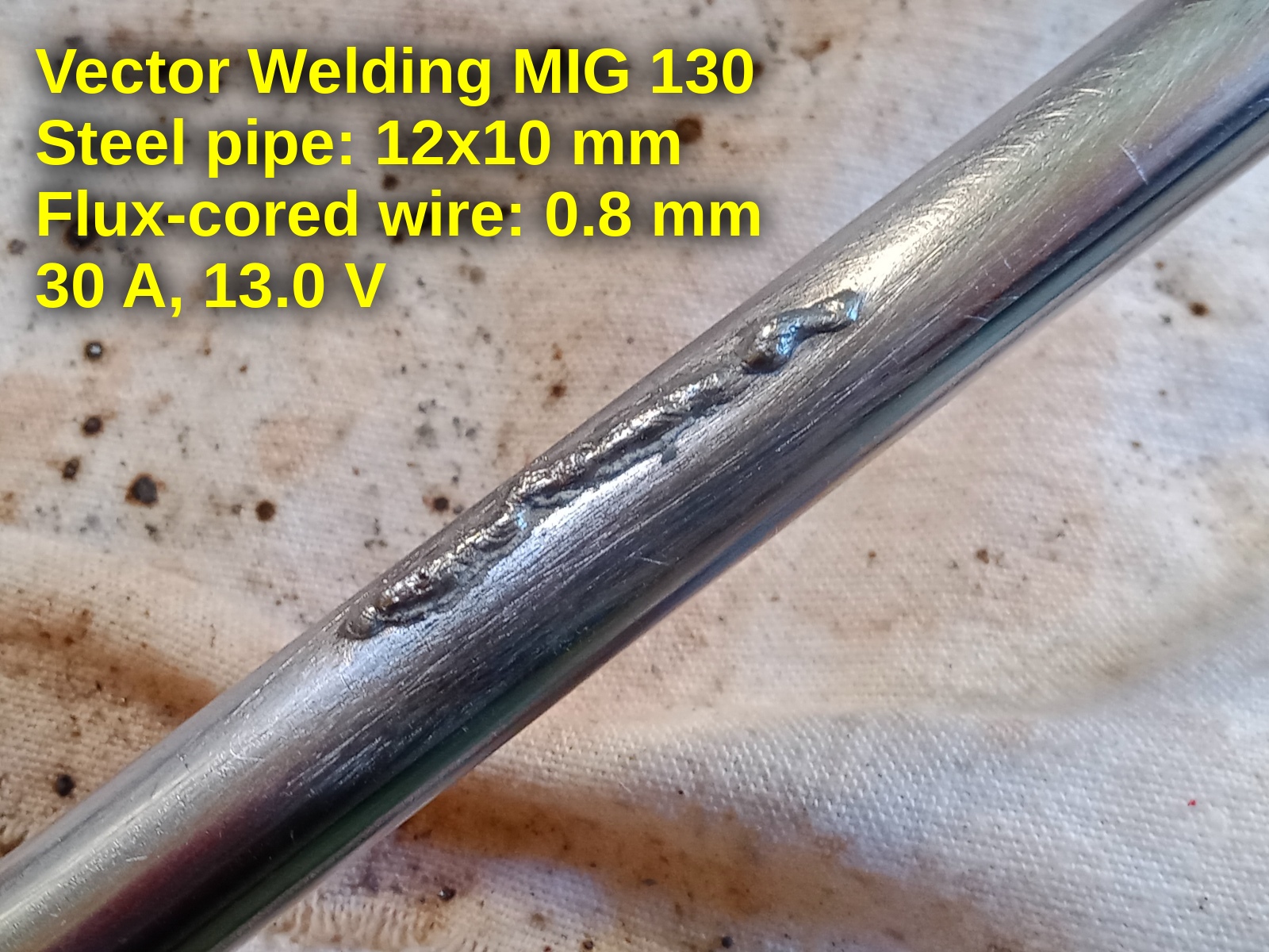
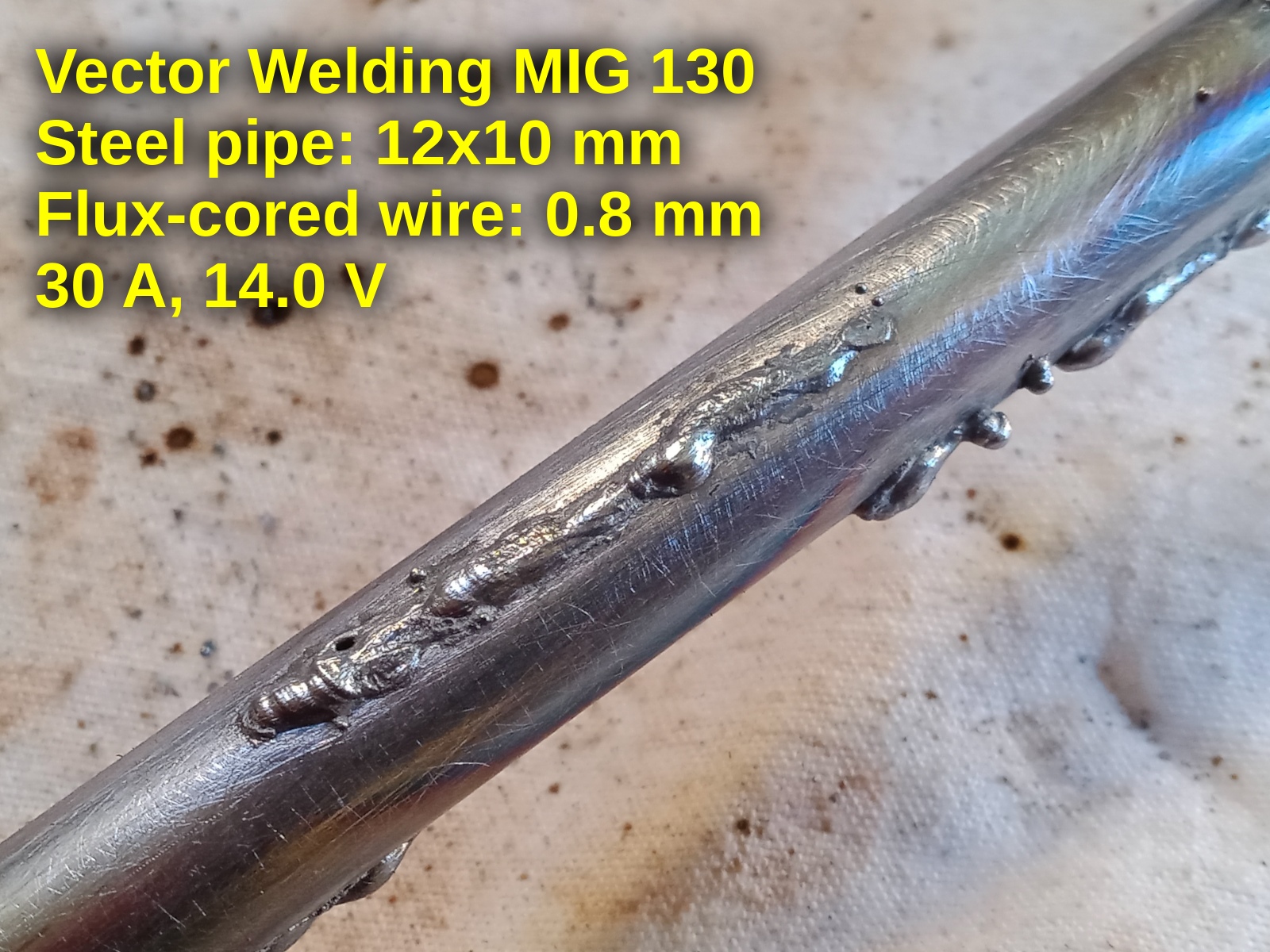
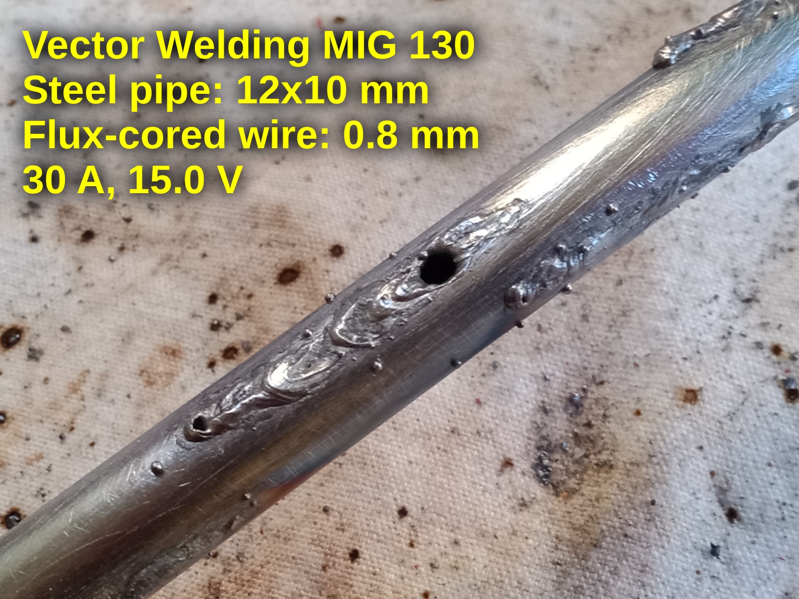
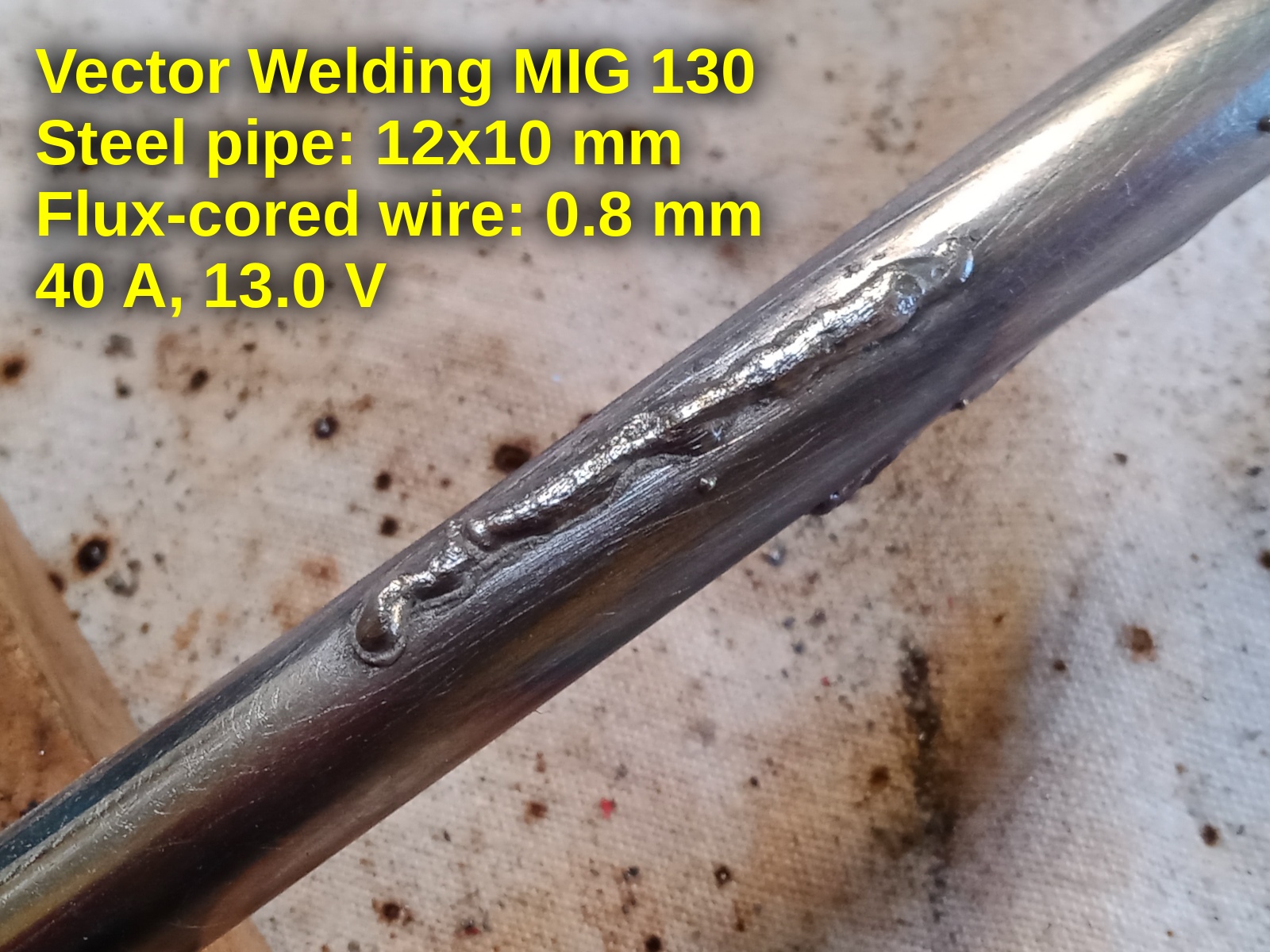
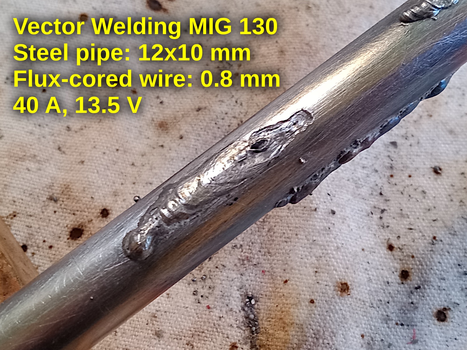
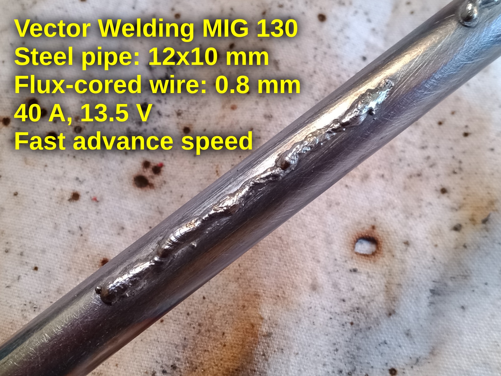
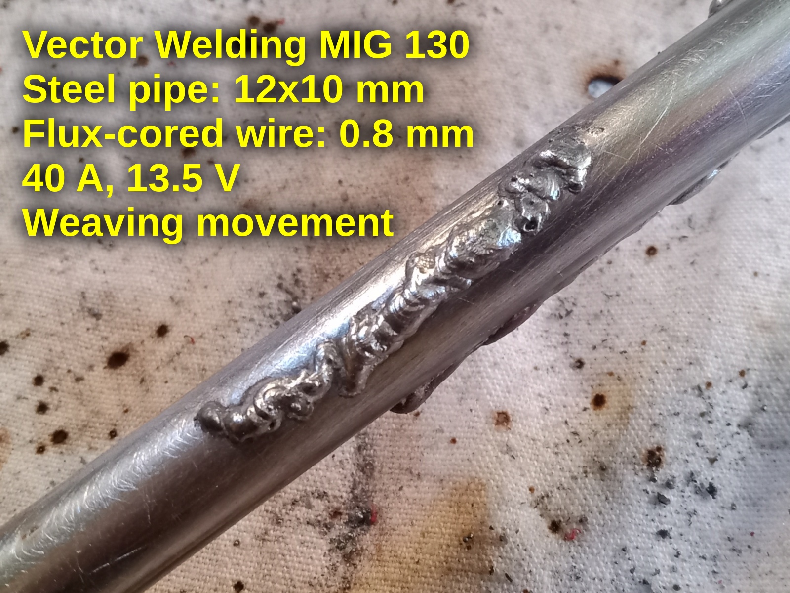
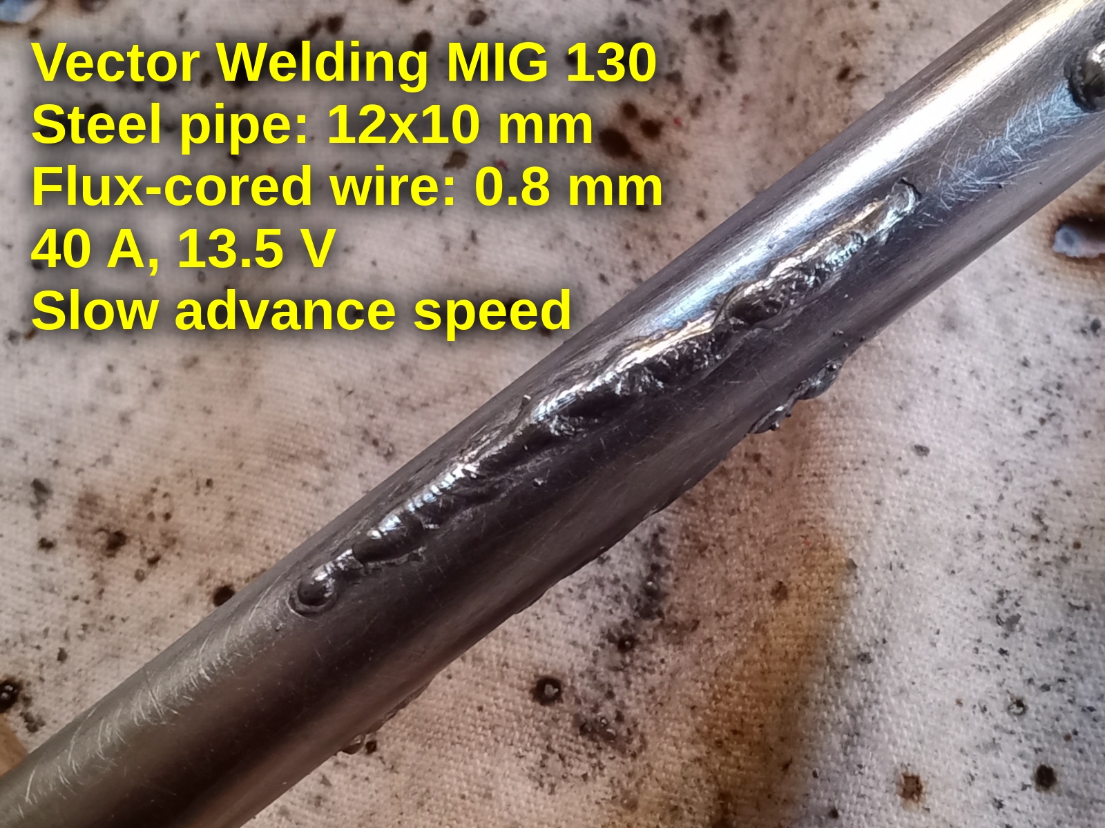
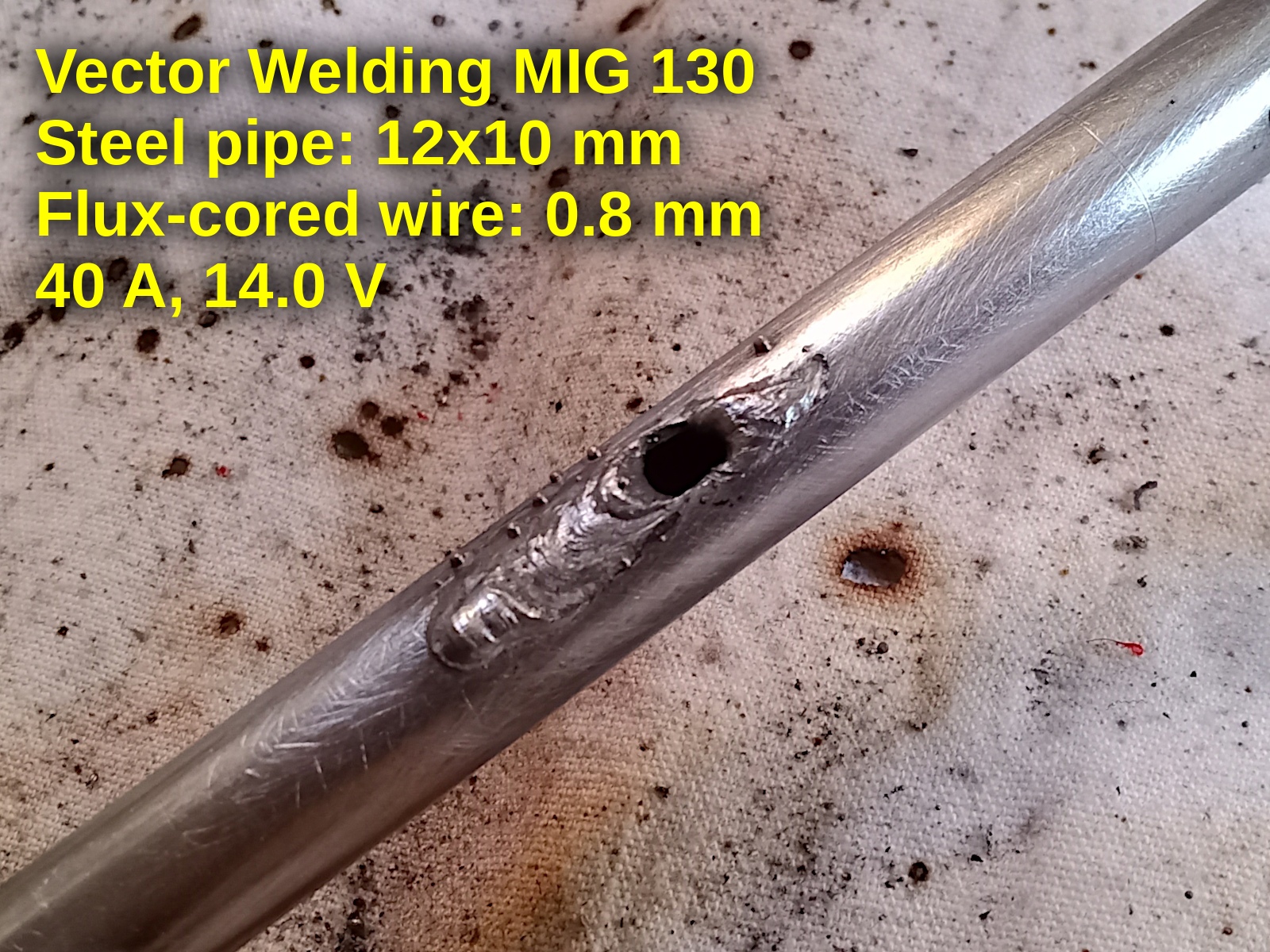
Welding samples: 1 mm thich pipe
These are some welding tests on a steel pipe (12 mm outer diameter, 1.0 mm thick), carried out at different current and amperage values. The wire used is a Telwin flux-cored 0.8 mm.
Welding samples: 4 mm thich bar
Some (bad) tests on a steel bar, 4 mm thick, with a flux-cored 1.0 mm wire:
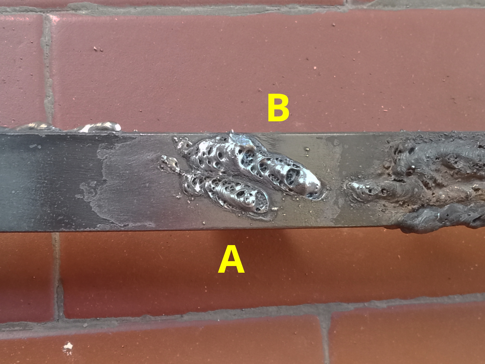

| Ampere | Volt | |
|---|---|---|
| A | 120 | 19.0 |
| B | 110 | 19.0 |
| C | 100 | 19.0 |
| D | 100 | 18.0 |
| E | 100 | 17.5 |
| F | 100 | 17.0 |
| G | 100 | 16.5 |